4.1편에서 SPI 예제를 살펴보았다.
혹시 이전 내용이 궁금하면 아래 링크를 클릭!
[nRF52832] 4-1. 예제 코드 파해치기 1탄 - SPI (tistory.com)
이제는 GPIO와 GPIO와 관련된 인터럽트 예제 소스인 GPIOTE에 대해 알아보도록 하자.
오늘도 프로젝트를 열기 전에 이번에도 Nordic Infocenter의 설명을 먼저 읽어보자.
https://infocenter.nordicsemi.com/topic/sdk_nrf5_v17.1.0/pin_change_int_example.html
nRF5 SDK v17.1.0: Pin Change Interrupt Example
The Pin Change Interrupt Example demonstrates interrupts on PIN_IN change. PIN_OUT is configured as output and toggled in the PIN_IN change interrupt handler. The application starts with configuring the pins and configuring GPIOTE to give an interrupt on P
infocenter.nordicsemi.com
설명을 하나씩 읽어보자
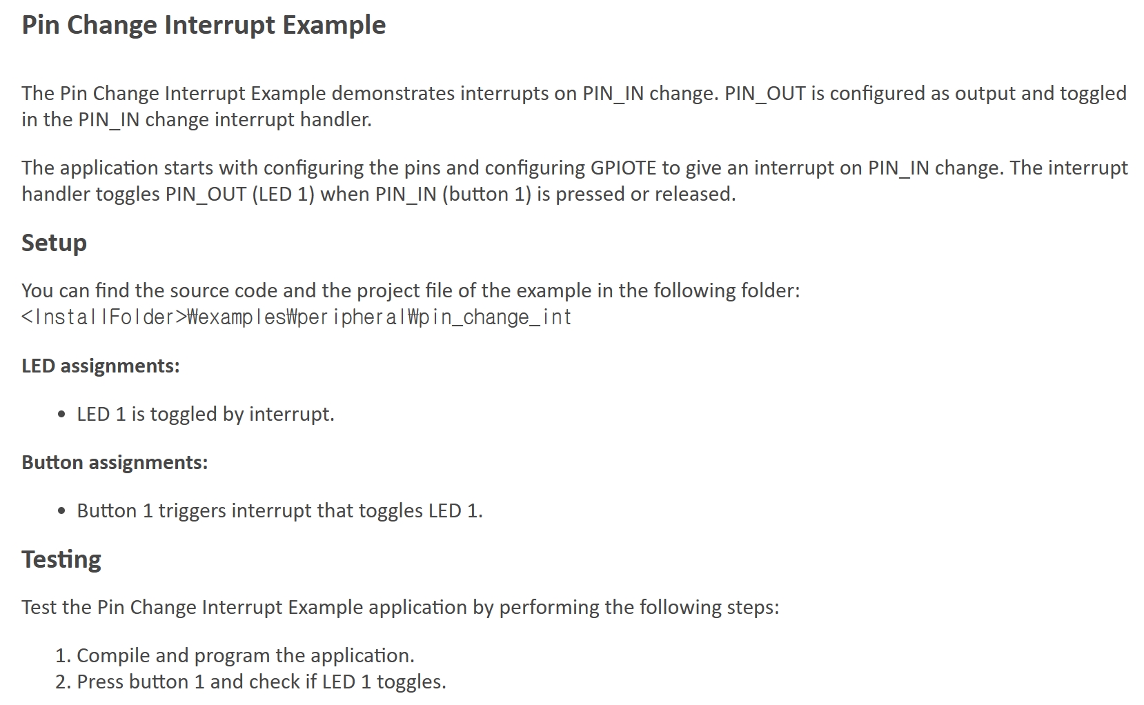
The Pin Change Interrupt Example demonstrates interrupts on PIN_IN change.
PIN_OUT is configured as output and toggled in the PIN_IN change interrupt handler.
The application starts with configuring the pins and configuring GPIOTE to give an interrupt on PIN_IN change. The interrupt handler toggles PIN_OUT (LED 1) when PIN_IN (button 1) is pressed or released.
PIN_IN의 변화에 따른 인터럽트를 통해 PIN_OUT을 변화시키는 예제이다.
여기에서 PIN_IN은 button 1번이고, PIN_OUT은 LED 1번이다.
Test the Pin Change Interrupt Example application by performing the following steps
1. Compile and program the application.
2. Press button 1 and check if LED 1 toggles.
테스트하는 방법은 간단하다.
1. 컴파일하고 프로그램을 다운로드한다.
2. 1번 버튼을 누를 때 LED가 Toggle 되는지 확인한다.
예제 소스는 이전 SPI 예제와 마찬가지로 examples 폴더 내 위치하고 있다.
peripheral>pin_change_int>pca10040>blank>ses에 위치하고 있다.
main.c - 초기 설정

gpio와 인터럽트와 관련된 헤더 파일이 include 되어 있다.
PIN_IN과 PIN_OUT도 define 되어있다.
이전 SPI 예제와 비교하여 간단한 구성이다.
main.c - in_pin_handler

gpio 인터럽트가 발생했을 때 수행되는 handler 구문이다.
나중에 필요에 따라서 해당 부분을 수정하면 된다.
여기에서는 이전에 설정된 PIN_OUT의 상태를 바꿔주는 역할을 한다.
void nrfx_gpiote_out_toggle(nrfx_gpiote_pin_t pin) {
NRFX_ASSERT(nrf_gpio_pin_present_check(pin));
NRFX_ASSERT(pin_in_use(pin));
NRFX_ASSERT(!pin_in_use_by_te(pin));
nrf_gpio_pin_toggle(pin);
}
nrf_drv_gpiote_out_toggle 함수는 nrf_rv_gpiote.h에 nrfx_gpiote_out_toggle이라는 함수로 선언되어 있으며,
nrfx_gpiote_out_toggle은 nrfx_gpiote.c 내에 정의되어 있다.
main.c - gpio_init 함수

메인 구문에서는 gpio_init 함수 외에는 별다른 작업은 수행하지 않는다.
그만큼 이번 예제의 핵심은 gpio_init 함수이다.
그럼 하나씩 살펴보도록 하자
nrf_drv_gpiote_init() 함수에서 기본적인 gpio 관련 초기화를 진행한다.

Output config를 위해 NRFX_GPIOTE_CONFIG_OUT_SIMPLE(false)로 선언한다. false 이므로 초기 상태는 low이다.
err_code = nrf_drv_gpiote_out_init(PIN_OUT, &out_config);
APP_ERROR_CHECK(err_code);
먼저 설정한 PIN_OUT을 output config로 설정한다.

Input config를 위해 GPIOTE_CONFIG_IN_SENSE_TOGGLE(true)로 선언한다.
True 이므로 정확도가 높은 버전으로 설정된다.
err_code = nrf_drv_gpiote_in_init(PIN_IN, &in_config, in_pin_handler);
APP_ERROR_CHECK(err_code);
nrf_drv_gpiote_in_event_enable(PIN_IN, true);
마찬가지로 먼저 설정한 PIN_IN을 input config로 설정한다.
인터럽트 신호를 받아야 되기 때문에 nrf_drv_gpiote_in_event_enable 함수를 이용하여 true로 설정해 준다.
GPIO 인터럽트 관련 예제 소스를 알아보았다.
내용이 잘못되거나 궁금한 점이 있으면 댓글로 남겨주면 확인 후 답변하겠다.
다음에는 BLE에서 데이터를 전송하는 예제를 알아보도록 하자
'개발 > BLE' 카테고리의 다른 글
| [nRF52832] 4-1. 예제 코드 파해치기 1탄 - SPI (0) | 2023.04.19 |
|---|---|
| [nRF52832] 3. 개발 관련 자료(Layout, SoftDevice, SDK) 다운로드 방법, 가이드 (0) | 2023.04.12 |
| [nRF52832] 2. IDE(Segger Embedded Studio) 다운로드 방법, 가이드 (0) | 2023.04.05 |
| [nRF52832] 1-2. 소자 선정 방법, 가이드 2편(시리얼통신, 수급, 패키지, 보험) (0) | 2023.03.29 |
| [nRF52832] 1-1. 소자 선정 방법, 가이드 1편(BLE, 내부 용량, FPU) (0) | 2023.03.22 |